NewsNEWS
Featured products
Contact Us
Understanding Submersible Pump Diagrams Effectively
2025-06-08Demystifying the Submersible Pump Diagram: Your Key to Understanding & Troubleshooting
Understanding Submersible Pump Diagrams Effectively
Understanding a submersible pump diagram is essential for anyone working with, installing, or maintaining these vital pieces of equipment. Whether you’re dealing with water wells, sump pits, ponds, or industrial processes, a clear submersible pump diagram acts as your roadmap. This guide breaks down these diagrams, making them accessible and highlighting their critical role.
Why the Submersible Pump Diagram Matters
A submersible pump diagram isn’t just a technical drawing. It’s a crucial tool. It visually explains how the pump works. It identifies every key component and shows how they connect. This knowledge is power. It helps with correct installation. It is vital for effective troubleshooting. It guides safe maintenance procedures. Without consulting the specific submersible pump diagram for your model, mistakes are more likely. These mistakes can be costly or even dangerous.
Core Components Illustrated in a Typical Submersible Pump Diagram
Let’s break down the parts you’ll almost always see in a submersible pump diagram:
-
Motor (Electric): This is the heart. The submersible pump diagram clearly shows the sealed, waterproof electric motor. It’s located at the BOTTOM of the assembly. This motor provides the power to spin the impellers. Its hermetic seal is critical, shown prominently in the diagram.
-
Intake Screen/Sump: Positioned just above the motor. The submersible pump diagram points out where water enters the pump. A screen filters out large debris. This prevents damage to internal components. Protecting this intake is key for longevity.
-
Impeller(s) and Diffuser(s): These are the workhorses. The submersible pump diagram depicts stacked impellers (rotating blades) and diffusers (stationary guides). Impellers spin, imparting velocity to the water. Diffusers convert that velocity into pressure. Multiple stages (impeller + diffuser pairs) create higher pressure. The diagram shows this stacking clearly.
-
Pump Bowl/Casing: This outer housing contains the impellers and diffusers. The submersible pump diagram illustrates how water flows through this pressurized chamber. The design is crucial for efficiency and pressure build-up. Materials (stainless steel, thermoplastic) are often noted.
-
Discharge Outlet: This is where the pressurized water exits. The submersible pump diagram marks the top connection point. This connects to the discharge pipe leading water to the surface or its destination. Size and thread type are usually specified on the diagram.
-
Power Cable: A critical sealed entry point. The submersible pump diagram highlights where the electrical cable penetrates the motor housing. Special seals (glands) prevent water ingress here. Failure at this point is catastrophic, shown as high-risk in the diagram.
-
Check Valve: Often integrated near the discharge or in the drop pipe. The submersible pump diagram shows this one-way valve. It prevents water from flowing backwards down the pipe when the pump stops. This protects the pump and prevents motor overloading.
-
Thermal Overload Protector (Internal): Safeguards the motor. While not always visually detailed, the submersible pump diagram usually notes its presence. It cuts power if the motor overheats, preventing burnout.
Different Types of Submersible Pump Diagrams
You might encounter several variations:
-
Exploded View Diagram: Shows all parts separated but aligned. This is excellent for identifying individual components for replacement. A parts list usually accompanies this submersible pump diagram.
-
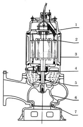
Cutaway / Cross-Sectional Diagram: Reveals the internal assembly. This is invaluable for understanding water flow paths. It shows how the impellers, diffusers, motor shaft, and seals interact inside the casing. This view is central to grasping pump operation.
-
Schematic Diagram: Focuses on the electrical system. It shows motor windings, capacitors (if used), the overload protector, and cable connections. Use this submersible pump diagram for electrical troubleshooting and wiring.
-
Installation Diagram: Provides specific guidance for setting up the pump. It shows recommended pit/sump dimensions, pipe connections, wiring routing, and safety considerations. Always follow the installation submersible pump diagram precisely.
Applications Dictated by the Diagram
The specific design shown in the submersible pump diagram reveals its purpose:
-
4″ Well Pumps: Diagrams show long, slender motors and multi-stage impellers for deep wells.
-
Sewage/Grinder Pumps: Diagrams highlight hardened impellers and cutting mechanisms for solids handling.
-
Sump Pumps: Diagrams often show simpler, single-stage impellers and float switch connections.
-
Fountain/Pond Pumps: Diagrams emphasize aesthetic design and sometimes filter attachments.
Using the Submersible Pump Diagram for Maintenance & Troubleshooting
This is where the submersible pump diagram becomes indispensable:
-
Identify Failed Parts: When a pump fails, compare symptoms to the diagram. Is it a seal leak (shown near motor/cable entry)? Is the impeller damaged (shown in the wet end section)? The diagram helps pinpoint likely culprits.
-
Safe Disassembly: Before taking anything apart, study the submersible pump diagram. Understand the order of components. Know how seals and bearings fit. This prevents damage during repair. The diagram is your step-by-step visual guide.
-
Correct Reassembly: Rebuilding a submersible pump requires precision. The submersible pump diagram ensures every seal, o-ring, spacer, and impeller goes back in the exact right order and orientation. Missing this can cause immediate failure or reduced lifespan.
-
Verifying Specifications: Need a replacement part? The part numbers and specs on the submersible pump diagram ensure you get the correct component.
Key Takeaways: Your Submersible Pump Diagram is Vital
Never underestimate the power of the submersible pump diagram. It is the authoritative reference for your specific pump model. Always locate and keep the original manufacturer’s diagram. Before starting any work – installation, inspection, or repair – consult the submersible pump diagram. Understanding the flow paths, component locations, and electrical layout shown in this diagram empowers you. It ensures safety. It promotes efficiency. It saves time and money on costly mistakes or misdiagnoses. A clear submersible pump diagram is truly the key to unlocking reliable performance.