NewsNEWS
Featured products
Contact Us
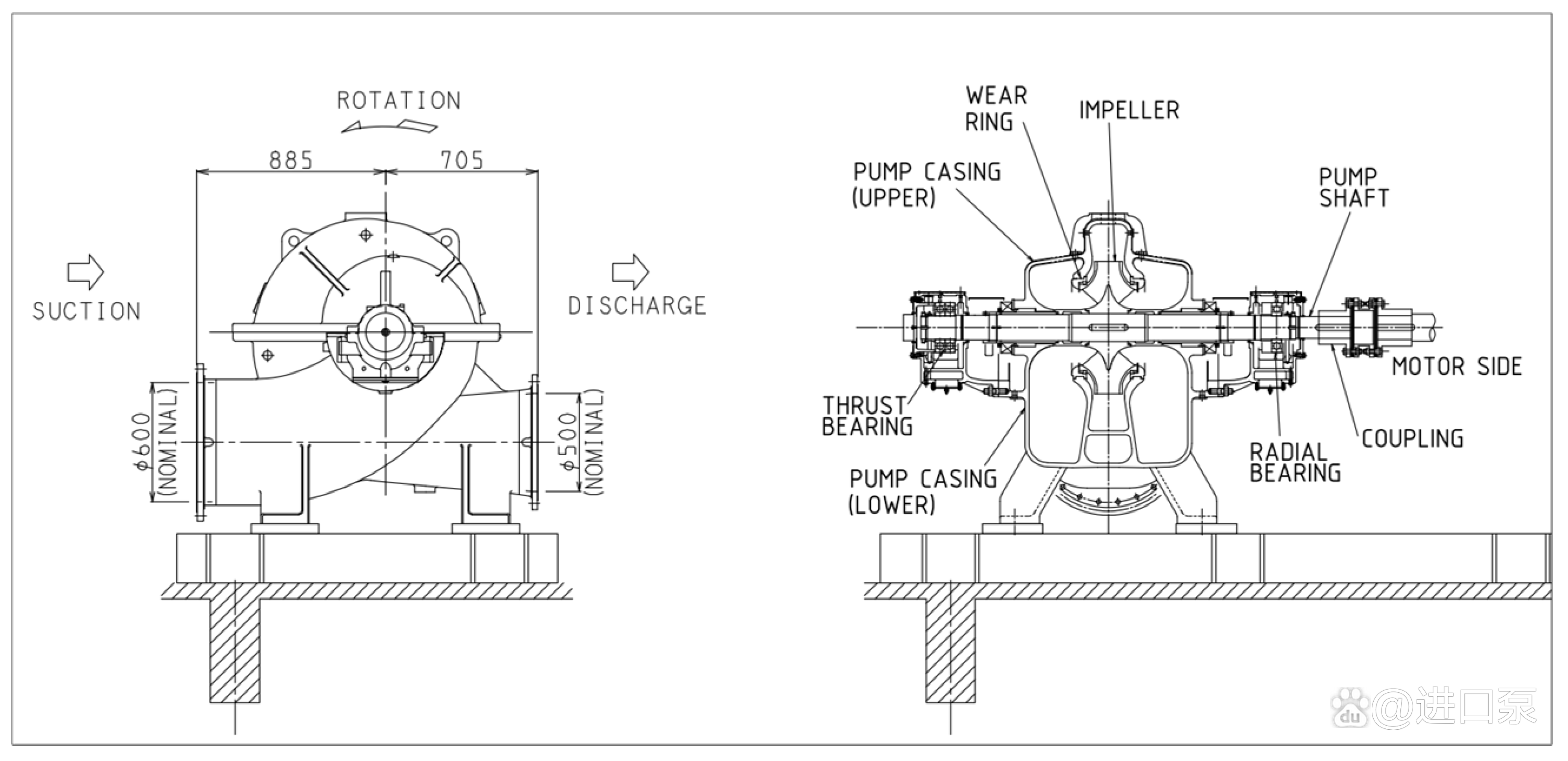
Centrifugal pump installation diagram
2025-07-11Master Your Pump Setup: The Critical Role of a Centrifugal Pump Installation Diagram
Installing a centrifugal pump correctly is vital. A well-planned centrifugal pump installation diagram is your essential blueprint. This diagram ensures safety, efficiency, and long pump life. Neglecting proper installation leads to costly failures. Let’s explore why this diagram matters and key installation steps.
Why a Centrifugal Pump Installation Diagram is Non-Negotiable
Every pump model and site has unique requirements. A detailed centrifugal pump installation diagram provides specific instructions. It covers exact dimensions, foundation specs, and piping layouts. Following this diagram prevents common errors. Errors like misalignment or improper suction piping cause vibration, cavitation, and premature wear. Relying solely on generic advice risks performance and safety.
Safety First: Preparing for Installation
centrifugal pump installation diagram carefully before handling any components. Ensure you have all necessary tools and lifting equipment rated for the pump’s weight. Never skip safety steps outlined in the diagram’s notes.
Foundation & Baseplate: Building Stability
centrifugal pump installation diagram specifies foundation type, size, bolt locations, and grouting details. Ensure the baseplate is perfectly level. Use precision levels during placement. Anchor bolts must be correctly positioned per the diagram. Proper grouting under the baseplate prevents movement and absorbs vibration. A stable base prevents costly misalignment issues later.
Pump & Driver Alignment: Precision is Key
Shaft alignment is paramount. Misalignment is a major cause of bearing and seal failure. The centrifugal pump installation diagram shows the pump’s final position relative to the driver (motor). Use proper alignment tools (laser or dial indicators). Perform alignment after the piping is connected but not tightened. Recheck alignment once piping bolts are fully torqued. Thermal growth must be considered as per the diagram notes.
Piping Connections: Avoiding Stress & Strain
Electrical & Auxiliary Connections
Connect wiring strictly according to the motor nameplate and local codes. The centrifugal pump installation diagram often indicates cable entry points and grounding requirements. Connect any auxiliary piping (seal flush, cooling, vent lines) as shown. Ensure seal chamber orientations match the diagram precisely. Verify rotation direction before final coupling guard installation.
Final Checks Before Startup
Double-check everything against the centrifugal pump installation diagram. Verify lubrication levels are correct. Ensure coupling guards are securely in place. Confirm all bolts are tightened to specified torques. Manually rotate the shaft to ensure it turns freely. Vent air from the pump casing and suction line. Inspect the entire area for tools or debris. Only then proceed with a cautious initial startup.
Conclusion: Your Blueprint for Success
A comprehensive centrifugal pump installation diagram is not just a suggestion; it’s your roadmap to reliability. Following it precisely prevents installation errors that lead to downtime, high energy consumption, and expensive repairs. Always demand and meticulously adhere to the manufacturer’s specific diagram. Investing time in perfect installation, guided by this crucial document, pays off massively in pump performance, efficiency, and longevity. Keep your centrifugal pump installation diagram readily available throughout the entire process.