NewsNEWS
Featured products
Contact Us
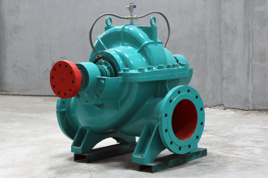
Centrifugal pump diagram
2025-07-11Demystifying the Centrifugal Pump Diagram: Your Essential Visual Guide
Why You Need a Centrifugal Pump Diagram
A centrifugal pump diagram serves multiple critical purposes. It aids in training new staff on pump operation principles. It simplifies complex hydraulic concepts visually. The diagram is essential for accurate troubleshooting and diagnosing failures. It guides correct installation and alignment procedures. Furthermore, it supports efficient maintenance planning and parts identification. Relying solely on text descriptions is far less effective than using a clear centrifugal pump diagram.
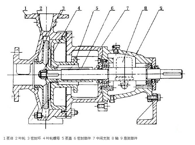
Key Components Illustrated
Every standard centrifugal pump diagram highlights core components. Understanding these parts is fundamental:
-
Impeller: The rotating heart of the pump. Vanes impart kinetic energy to the fluid. Diagrams clearly show impeller type (open, closed, semi-open) and rotation direction.
-
Casing (Volute or Diffuser): Surrounds the impeller. The volute casing converts kinetic energy into pressure. Diagrams illustrate how the volute’s shape gradually expands to reduce velocity and boost pressure.
-
Shaft: Connects the impeller to the drive motor. The diagram shows shaft orientation and support points.
-
Bearings: Support the rotating shaft, minimizing friction. Their location and type (e.g., ball, sleeve) are marked.
-
Seals (Mechanical Seal or Packing Gland): Prevent fluid leakage along the shaft where it exits the casing. The centrifugal pump diagram details seal arrangement and flush plans if present.
-
Suction Eye: The inlet point where fluid enters the impeller. Diagrams show its size and position relative to the impeller vanes.
-
Discharge Nozzle: The outlet where pressurized fluid exits the pump casing. Its size and orientation are clear on the diagram.
-
Wear Rings (Optional but Common): Installed on the casing and/or impeller to create a tight clearance seal. Minimizes internal recirculation and efficiency loss. A detailed centrifugal pump diagram will include these if applicable.
Understanding the Flow Path
A good centrifugal pump diagram vividly depicts the fluid’s journey:
-
Fluid enters axially through the Suction Inlet.
-
It flows into the center (Suction Eye) of the rotating Impeller.
-
The impeller vanes accelerate the fluid radially outward. Centrifugal force flings it towards the casing.
-
High-velocity fluid enters the expanding Volute Casing.
-
Within the volute, fluid velocity decreases. This converts kinetic energy into useful pressure energy.
-
Pressurized fluid exits through the Discharge Nozzle into the system piping.
How to Read a Centrifugal Pump Diagram Effectively
Start by identifying the main sections: suction side, rotating assembly (impeller/shaft), casing, discharge side, and sealing system. Trace the fluid path from inlet to outlet. Note the relationship between rotating parts (impeller) and stationary parts (casing, wear rings). Pay close attention to arrows indicating rotation direction and flow path. Cross-reference part numbers with a pump parts list for maintenance. Understanding the centrifugal pump diagram unlocks safe and efficient operation.
Applications and Importance
Referencing the centrifugal pump diagram is essential during installation, commissioning, routine checks, troubleshooting vibration or low flow, performing maintenance tasks like seal replacement, and ordering correct spare parts. It ensures everyone works from the same accurate visual reference. Always consult the specific pump’s diagram for precise details. A clear centrifugal pump diagram is fundamental knowledge for anyone working with these ubiquitous machines. Keep it accessible!